For live blog and possibly more current blog with integrated video visit:
https://nickstedman.wordpress.com/2008/11/28/adb-after-deep-blue/
ADB is a modular robot for tactile intimacy. Loosely resembling a snake the object mechanically responds to the presence of skin, attempting to get as close to the surface as possible. The robot quickly comes to rest on a still body, so continued animation depends on a participant’s active engagement. Stroking or rubbing the robot will result in it pushing back and occasionally grasping onto a body part. Participants may experience the object at their leisure. They can play with the device, exploring how it feels, and how it responds to their touch.
Inspiration for the project is drawn from Deep Blue, the computer that defeated former world champion Gary Kasparov in the now legendary 1997 chess match. This event marked a tipping point in the popular imagination when the suggestion of a machine intelligence became tangible. Prior to Deep Blue machines had already demonstrated superior brawn, and superior ability to process information measured in MIPS, but these strengths were always used for human service. Chess is different. Clearly chess adheres to a logic to which computers are disposed, but it is a game created for the entertainment of people. It is generalized abstraction of wars fought throughout history complete with characters and relationships between them. And for the players, chess brings a waves of emotions experienced through the gains and losses of the imaginary battle they fight. In the words of Emma Pierson, a 16 year old competitive chess player, “A chess game is a microcosm of life, decades of joy and tragedy condensed into a few hours.” To what end then should a computer be made to play this game? Surely, it’s not because machines have a deep emotional need to play. They derive no sensations in any way to which people can relate. It’s also not merely explained as practice for players. The entire match between Kasparov and Deep Blue was itself a sensation, more exciting than most ranked competitions between grandmasters. No, Deep Blue was created to demonstrate that presently a machine is not only competent but even superior in a domain considered distinctly human.
In the grand scale of possible redundancies, chess is none too scary an obsolescence. What is more worrisome are the many lingering questions. Why is the replication of humane behaviors interesting? What’s next? Are there any aspects of being human that can’t be tasked in a machine? If not, where does leave us, and why on earth are we building them?
In the decade that has passed since Deep Blue’s triumph, machines have continued to be extended into once human domains. Hedge Funds automate the allocation of investors’ money through the use of Quants, computers containing complex models of the stock market, tracking flows of money, speculating how to make profit, and then carrying out trades. At quite the other end of the utility spectrum Wim Delvoye created Cloaca, a machine capable of defecating.
ADB extends these incursions into a different sphere of life. It has been created to share intimacy with a person. Intimacy in this light is treated as a domain permeable to computation. The approach taken is to limit the interactions to non-linguistic, physical exchanges. Through programmed movements and responses which gently stimulate the body, ADB arouses its human interactors.
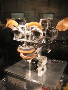
The approach differentiates itself from other related efforts. Cynthia Breazeal uses mimicry in her robots to elicit the participant’s emotions. They have eyebrows and lips though no flesh to warrant these features. ADB is non-representational. It’s visual features have been reduced to a single monotoned geometry. The geometry was selected, as were the technologies, for the behaviors they enable, the rubbing, squirming and wrapping which draw the robot closer to a person’s body. It is a significant difference, because the effort is to create intimacy between human and machine. By moving away from mimicry and towards a form that embraces its artificiality yet still complements the human body there are opportunities to learn how to create an artificial intimacy. In this sense ADB is much more in line with some contemporary body-centric sex toys with which representations of anatomy are eschewed for ergonomic design. This is not to say that ADB is unlike existent creatures. Viewers quite naturally call it “the snake”. The point is its form follows its function.
The machine is composed of a linear series of triangular modules, each containing a motor, several sensors, and accompanying electronics. A module’s sensors include an encoder to learn the position of the motor, a current sensor to know the force that the motor is exerting, and touch sensors for detecting skin contact. Dynamic shapes and patterns are formed by coordinating the modules’ movements in response to sensor data.
Exhibition:
ADB is being exhibited at Space Gallery in London, England from November 7th to December 20th. The show is called “Schematic”, and profiles the work of several Canadian new media artists who create their own electronic devices and sculptures as their artwork. Please have a look at the exhibition blog, and read the Curator’s essay on the show.
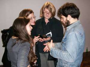
ADB is available at front desk of the gallery. Patrons request the object, and then wander the gallery with robot in hand. In this way the site of interaction becomes the body. The audience doesn’t acquire a acquire a distanced removed view, unless they are seeing another individual holding the machine. It is always experienced in relation to a person.
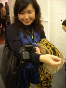
Here are several images from the opening (click for enlargements).
Design:
ADB was originally conceived and sketched out in 2003 as a derivative of the Blanket Project, a robotic blanket intended as a sensual companion. While the Blanket Project allowed a number of interesting technical and conceptual explorations to begin, it never culminated as a finished device. It lacked sensors for example, necessitating automated behaviors, or remote control in place of autonomy. In order to resolve many of ideas spawned by the Blanket Project, I decided to build a simpler, smaller device in a manner that would make it a robust platform for exploring artificial sensuality.
The initial blueprint was drafted in 2005, with illustration help from Jennifer MacDonald. This along with other drawings and projects were shown at Oboro in Montreal in 2006. Exhibition of the blueprints served an important role of testing audience interest in the project, which reinforced confidence in the decision to proceed in further developing it. I chose to work on ADB for my MFA thesis in Media Study at the University at Buffalo, which was not to begin in earnest until the fall of 2007. At that stage I imagined the finished device would be a very adept partner. It would use a variety of machine learning to learn its partner’s sensual preferences, and it would be dexterous enough to manouver around an entire body. Here is the original proposal. My thesis committee thankfully tempered my expectations. We agreed that if the robot could wrap around an appendage when in contact with skin then that would suffice for my thesis project requirements.
As a proof of concept, the robot was modeled in a simulated physical environment to test several aspects of the design, including the mechanics, the sensing and the machine learning. For the latter, genetic algorithms (GAs) were selected for their ability to evolve behaviors in modular robots. They had been successfully used by Karl Sims to evolve virtual creatures who were composed of simple primitive geometries akin to ADB’s design. They had also been used by Kevin Dowling to evolve behaviors in simulations of snake robots, although he later opted for Probabilistic-Based Incremental Learning. The simulation was programmed in Python. ODE was used for the physics modeling, OpenGL to draw the graphics, and Pygene for the GA. A basic environment was constructed with gravity, friction, collision detection and a flat infinite surface upon which the robot could ambulate. The robot’s geometry was built from a series of repeated prism-shaped modules, each one inverted to the next in the chain, and joined at the center of their touching facets. These joints acted as the motor. A sensor for measuring the distance the robot travelled betweened two points was also simulated. This was selected as a simple means of providing feedback into the system while learning how to implement the GA. The initial task then was to evolve gaits (patterns of switching the modules’ motors off and on in either direction) that would cause the robot to move along the flat surface, maximizing the distance it travels over time. The simulation was worked on from September 2007 to January 2008, when the robot started to successfully develop gaits. While the simulation could be further developed, it demonstated that at a minimum the robot should be able to mechanically manouver, and that a feedback loop between sensing, processing and actuation could likely be used to automate ADB. So the project was advanced to next stage of design.
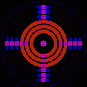
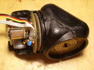
The next phase was to create the detailed design of the robot in three related areas, the mechanics, the electronics, the body. First the mechanical system was designed as it affected the other two areas to a large extent. The robot is composed of repeating segments, only the first and last varying from the others, and then only slightly. This meant only three modules needed to be designed. Mini-gearhead motors were sourced which have high torque, are small in size, run at low voltages, are affordable. One would be placed in each. Since the object would be battery powered then it became important for it to be easily rechargeable. That meant that electricity had to flow from one central access point to all the modules, through rotating linkages. The same requirement existed for a data line, so the modules could communicate with each other. The only way to do this is with a slip ring of some variety. Those that were looked at proved to be too expensive and have the wrong dimensions, so a slip ring was designed from scratch. It is made from two circular printed circuit boards (PCBs). One disk is mounted to the chassis of the motor, and held in a fixed position relative to the module and is wired to the main circuit. The disk has a line of brushes on it’s top surface which are used to make a rotating conductable connection to the other disk. The other disk connects to the rotating shaft of the motor. It has ring shaped copper traces which rub against the brushes of the other disk as it rotates, maintaining contact. Pin headers are soldered to the rings on the top side of the disk which then snap into the agacent module. This serves the double purpose of creating a mechanical connection between modules such that one module can rotate its position relative to the next. The three pin connection between modules also allows ground, power and data to be shared between modules. The slip ring is also designed to act as the motor encoder. Three additional rings on the the shaft disk are segmented in an even pattern of 32, such that when a brush comes into contact with a segment it receives an electrical pulse which can be counted by the main circuit to know how much the motor has turned. By having two segmented rings slightly offset, the direction and angle is determined. A third ring has only one segment on it, for callibrating through absolute encoding.
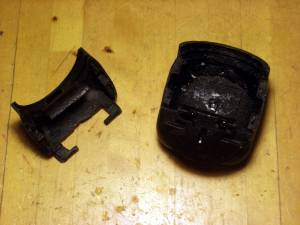
Once the slip ring was ready a shell could be designed around it and the motor. Since the model for the shell was to be fabricated from a rapid prototyping machine, meaning that a high level of detail could be achieved, it became feasible to minimize the number of components by designing mechanical features directly into the shell. For example the motor attaches to the one of the slip ring disks which is held in place by a clasp designed into the shell. Each module’s battery is similarly held in place. To relieve stress encurred along the motor’s shaft from the weight of other connected modules, each module was designed with a male and female coupling ring which act like a bearing, distributing stress throughout the shell and away from the shaft. The shell also contains divots for the placement of copper sheet which acts as the touch sensing surface. The shell is composed of two halves which neatly fit together interlocking so as to not fall apart. Dividing the shells in two parts was necessary to make molding more easy, and also to fit the various components within. The robot is designed to be assembled by snapping the modules together.
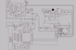
With the shell designed, dimensions for the main circuit that would control each module could be determined. As the robot was small, the circuit needed to be compact which necessitated using the smallest packages available for most of the components. The circuit contains a PIC microcontroller at the heart of each which runs the main program that determines the module’s behavior. It also controls all the peripherals and communicates with other modules. The motor is controlled through a low-voltage H-bridge. The current consumed by the motor is probed through a shunt resistor, and amplified by an op-amp. Current feedback reveals how much force the motor is exerting which can be used as an additional tactile sensor. The circuit was designed to use a hall-effect sensor for this purpose, but was later bypassed as the particular part did not do the job. A touch sensing IC is used to determine if a person is in contact with each of the three exposed facets of a module. Each sensor emits a capacitance field from a connected metal plate. When the field is interrupted by a grounded conductor, such as a body it triggers the sensor. The advantage of this technique is that the field can be emitted through other materials, and so in this project the sensors were able to be hidden inside the object and yet detect contact with skin. That option provided flexibility with the asthetics. The circuit also connects to slip disk.
The circuit is powered with a rechargeable RC123a lithium-ion battery. The batteries contain their own short-circuit protection circuits which came in handy during the debugging stage. An integrated circuit (IC) for recharging the battery was incorporated into the main board. When 5 volts is presented on the main power lines that run throughout the robot, each module’s recharge IC automatically begins recharging their respective battery, and signals to the microcontroller which is programmed to idle the motor for the duration of the recharge in order to limit the power consumption.
Here is the Bill of Materials for the main circuit.
Fabrication:
There was some overlap between the design stage and fabrication. Many elements had to be reworked a number of times which required redesigning the parts. Also aspects of the fabrication were outsourced, so while one part was being built, the time was used to design the next part.
The shell was first printed on rapid prototyping printer at the University at Buffalo. The part was rendered once in a durable ABS plastic, which was unable to create smooth curves and was expensive, so the second version was made with a hardened starch. The starch required some sanding, and while it rendered smooth curves its accuracy was off, often adding as much as 20 thousands of an inch of extra material, which is a lot when working with tight tolerances. So the part was filed down to the correct dimensions. It also comes out from the printer rather rough, and so a general sanding is required.
The starch shell served as a model which was reproduced in a durable resin using classic casting techniques. One side of each part was covered in plasticine and placed into a plastic container. It was then coated in a mold release and silicone rubber was poured over top. Once the silicone firmed up, the part was flipped over in the container, the plasticine removed, sprayed and then more silicone poured on. The resulting mold is a negative impression of the part. A two part liquid resin was mixed with black dye and poured into the mold to duplicate the original model a dozen times.
The PCBs for both the main circuit and the slip rings were outsourced to PCB fab houses. This was opted for over home fabrication in order to ensure a standard quality and also because it was relatively affordable to do so. BatchPCB was used for main boards as they are very affordable but they take over a month to produce the parts. Advanced Circuit’s barebones service was used for the slip rings as they can produce boards without a solder mask, which was used to leave the traces exposed for contact with the brushes. Unfortunately, Advanced Circuits does not cut out the parts which meant that disks had be cut out and sanded by hand, providing an opportunity for human error.
The slip ring is afixed as previously described, one disk to the motor chassis and the other to the shaft. The shaft disk is fastened to a collar which screws onto the shaft. Unfortunately the screw tends to loosen over time, so it became necessary to solder it to the shaft in order to make the connection firm. The shaft disk also needs to be slightly smaller so it can turn freely without rubbing against the shell. The motor body has to be fixed to the shell through the chassis disk so that the motor and module move as one, so epoxy is used to hold it in place in the groove which had been designed for it. Short lengths of music wire are used for the brushes. They are soldered to the chassis disk and then bent so that they spring up against the rotating shaft disk. It became necessary to attach some pull-down resistors to the encoder as these were overlooked in the main circuit design. Breakaway pin headers are soldered to the top of the shaft disk. These snap onto pins on the adjacent module to share power and communication with it.
Electronic components were purchased at Digikey. They were soldered by hand to the boards. Because they were very small packages it was necessary to coat the board in a liquid flux that causes the solder to easily adhere between pins and pads. Several problems were revealed on the prototype of the main board and so corrections were made and a new batch was printed, tested and worked successfully with some minor bugs, so all remaining were soldered.
All the circuits are the same except for one at the head of the robot. It has no motor, and it has an Xbee wireless transceiver which has been tested but is not implemented at this stage. On one module a power adapter receptacle was connected to power lines, and then afixed to the shell through a drilled hole. A 5v DC power adapter plugs into this module. The voltage passes on to all the modules through the slip rings. This socket makes recharging the batteries very simple, just plug it in.
The circuits were then programmed. Essentially, the limited objective at this stage was to have the snake seek out skin contact all along the surface of its body when it was touched. In order to simplify the programming, each module was to determine it’s own motor’s behavior with input from the rest of the robot. The overall behavior would then be an emergent property of the individual units’ collective actions. Since two adjacent modules share a motorized joint, which determines their position relative to the other, they are programmed to share control over the joint. If either of the modules is touched (but not both) then the motorized joint begins to spin in a random direction. It continues to spin until the other module comes into contact with skin, at which point the motor is shut off. What emerges from this behavior is that if a single module is touched then the two adjacent modules will turn until they find contact with the skin, in turn causing the next two modules in sequence to start turning until they also come into contact with the skin, and so on until the entire robot finds contact. Because skin contact for a particular module may not always be physically possible in the context of the positions that other modules have assumed, if a module has not made skin contact after a period of time it will send out a reset trigger to all the modules telling them to try another configuration. In that case, all that have already found skin contact will begin to move again for a short period. Finally, because of the long segmented shape and with many modules moving randomly with respect to each other, the robot may easily end up curled and tangled into itself, to prevent this the circuit is always monitoring its encoder and current sensor. If it finds that it is consuming too much energy, or that it’s position is not changing when it should be then the spin direction is reversed. This has the effect of quickly undoing potential entanglements.
Click here to download the code for each module, and the code for the head module. They are written in C using the CCS compiler and Microchip’s MPLab IDE.
With the various parts fabricated and the circuits programmed. The robot can be assembled. The two parts of the head shell are joined together, then the next module is assembled around the head’s base, and so on down the line. While this method is inconvenient during the debugging stage. It makes for sturdy connections between modules helping the robot to stay in tact. Unfortunately, a proper latch wasn’t developed to keep the modules firmly together, as a result black dyed epoxy is used to keep them in tact.
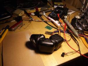
Getting there
Conclusion:
ADB is presently capable of some responsive tactile interactions with a human participant. It has an appropriate technologies, shape and program to carry out such behavior. The exhibition at Space Gallery demonstrated that people will intimately engage a machine, and are even willing to care for it. They are also interested in experimenting with it in more private situations. ADB is not a science experiment. It does not prove anything. In fact, it provokes more questions than it answers. Are the sensations it elicits empathy? How much empathy can people extend towards a machine? Could the machine be made to have a long-term relationship with a person, learning their preferences and displaying its own ideosynchratic behaviors that might be called character. Could such a relationship hold a meaningful place in someone’s life, on par with the kind of empathy felt for another person? If so, then does that mean that machines are capable of intimacy? If not, why not? In thinking more about Deep Blue, Daniel Dennett responds to those who would make light of the computer’s acheivement. “The verdict that computers are the equal of human beings in chess could hardly be more official, which makes the caviling all the more pathetic. The excuses sometimes take this form: ‘Yes, but machines don’t play chess the way human beings play chess!’ Or sometimes this: ‘What the machines do isn’t really playing chess at all.’ Well, then, what would be really playing chess?” In this light, we may wonder if a machine behaves in a way that is experienced as intimate, and others recognize it as intimacy, then doesn’t this qualify as intimacy?
Future Work:
At this stage, ADB is essentially a platform just at the beginning of being explored. The motors turn, the sensors detect, the batteries charge and software relates these elements together. It presently runs a simple program to determine its behavior relative to a user. Many enhancement could be made. There are some structural design changes that would improve the system. It would be useful if the robot could be snapped together on the fly without dissassembling individual modules. This could be accomplished by using strong magnets to hold the modules together. Another improvement would be to create access to the programming header, again without having to dissassemble units. It would be interesting to explore machine learning techniques in more depth, especially Neural Networks. Perhaps the robot could learn user preferences over time, and customize its behaviors for them. In order to explore the potential of software it would be useful to implement the wireless transceiver that is built in the robot, such that it streams sensor data to a desktop computer, where it gets processed, and control signals sent back to the device. Such a system would allow the code to be more quickly adapted then to dissassemble the robot and upload firmware on each module for any change. As an extension of this system, the simulation of the robot should be brought into closer alignment with the real device, emulating all the same sensors, using the same API to control both, and modelling interactions with a body. By doing so, then tests could be run harmlessly on a simulation before putting the real robot through the paces.













Pingback: ADB (after Deep Blue) - hardcopy « Nicholas Stedman Documentation
where can I read about microcontroller in your blog?! I have searched about the word “atmel microcontroller” and you blog appeared to me
That’s odd, I didn’t use Atmel chips I used Pic chips and I didn’t talk about them too much. There’s only one entry on my blog with less than a paragraph about micros, so what you see is what you get.